
Introduction
The Bus Pirate is an open-source hardware hacking platform designed for interfacing with various protocols and hardware interfaces, serving as the “Swiss Army Knife” of hardware hacking. I always keep one with me as you just never know when you will find yourself trying to hack some electronics and need something that talks JTAG or some other protocol. The initial release of the Bus Pirate was in 2008, with v3 coming shortly after in 2009, then v4 in 2011. Each time there were various improvements and additional features. Development for the Bus Pirate 5 has been in the works for some time and finally became available in 2024. The Bus Pirate 5 has some notable features, including:
- The hardware platform (and firmware) was ported to an RP2040
- An LCD screen, complete with connection details (including voltage)
- 1 Gbit NAND flash chip, accessible via the SPI bus or as a USB storage device
- Eighteen programmable LEDs
- Several different options for connector configurations
Note: Hackaday’s article titled “Hands On: Bus Pirate 5” includes even more information.

The Bus Pirate was designed by Ian Lesnet of Dangerous Prototypes. Be certain to listen to a recent podcast interview with Ian on the Unnamed Reverse Engineering Podcast – Episode 69 – Canned Cheese and Onion Rings (they do explain the references to canned cheese and onion rings, in addition to several other food references).
I’ve used the Bus Pirate 5 in various small projects and debugging exercises and really find the various cable kits useful. The following kits are available:
- Probe Cable Kit – Probe hooks come in handy for different types of applications, and while I have not yet used the milled breadboard adapter pins they really neat (and even milled to be square in the middle, rather than round, so they don’t roll off the table).
- Auxiliary Cable Kit – I really like the color coded crimp housings, especially if you are connecting to pins in tight spaces.
- SPI Flash Adapters – Sadly I did not order this when I placed my original order and am waiting for it to arrive.
- KF141 quick connect adapter with silkscreen – Sometimes you need to quickly connect and disconnect wires, and this adapter has spring retention clamps and clearly labeled connection points.
Accessing and Updating Firmware
To access the Bus Pirate I like using “tio” (Available for Linux/MacOS/Windows) and access as follows:
$ tio /dev/ttyACM0 -b 115200
[12:10:06.750] tio v3.3
[12:10:06.750] Press ctrl-t q to quit
[12:10:06.751] Connected to /dev/ttyACM0
VT100 compatible color mode? (Y/n)> Y
The Bus Pirate will ask if you would like to enable color mode, which is handy as the colors in the terminal correspond to the colors on the cable connections. Use the “i” command to get the version of the running firmware:
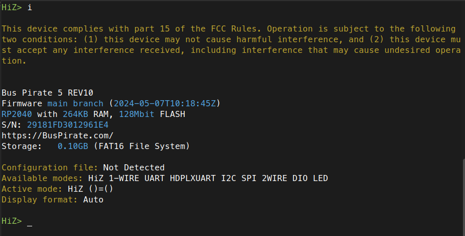
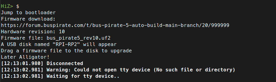
Next, you can download the latest versions of the firmware from the Bus Pirate forum. Firmware releases come out on a regular basis, so its a good idea to check before you start interfacing with hardware. Use the “$” command to put the Bus Pirate in bootloader mode:
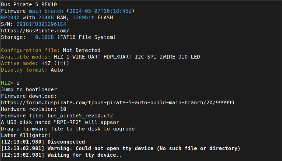
Next, copy over the firmware to the drive that appears and wait for the device to reboot. Then run the “i” command again and verify that the upgrade was successful:
Basic Tasks: UART
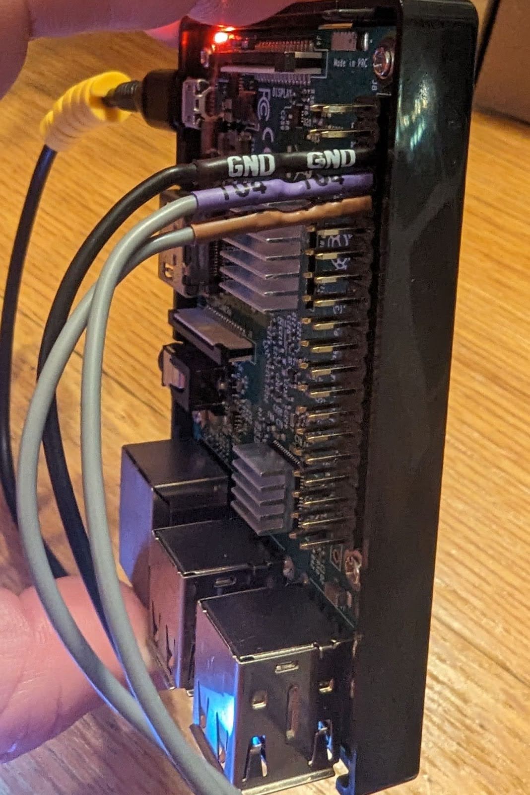
While there are several different options for interfacing with UART I like the Bus Pirate 5 because the round shrink-wrapped connectors are pretty universal and can connect to different types of pin headers (even ones with smaller spacing) and the LCD display makes it easy to keep tabs on voltage (yes, you can also use a multimeter, but its nice to keep tabs in real-time using the same device and displaying the voltage at all times). I connected the GND, TX, and RX to a Raspberry PI:
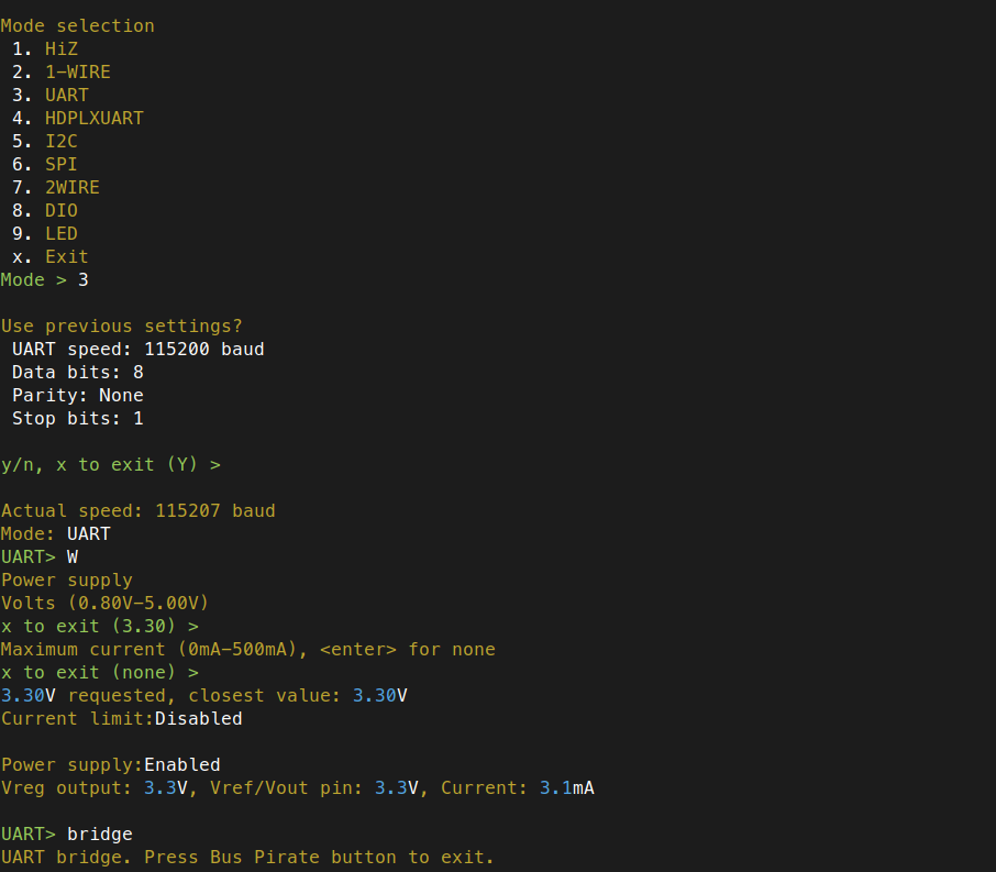
Next, I entered UART mode, set the correct settings, enabled the power supply, and triggered the UART bridge to see the Raspberry PI boot messages (and get a serial console):
You will need to do some additional setup to replicate this setup, depending on which Raspberry PI you have and which operating system you choose to install. This article titled “Enabling UART on Raspberry Pi: A Step-by-Step Guide” is a good place to start. I did also use a similar setup to gain access to the UART functionality on a Raspberry PI 5 debug port. For that I purchased a Raspberry PI Debug Probe Kit for $12.00, which comes with its own hardware (an RP2040) for UART and SWD (Serial Wire Debug) and the appropriate cables and connectors. You can use the included cables in the above kit to attach the Bus Pirate to the Raspberry PI 5 debug port via the Dupont wires and connectors (Note: You may also want to pick up a couple of these cables for interfacing with 3-pin debug ports and/or to have spares).
Reading SPI Flash
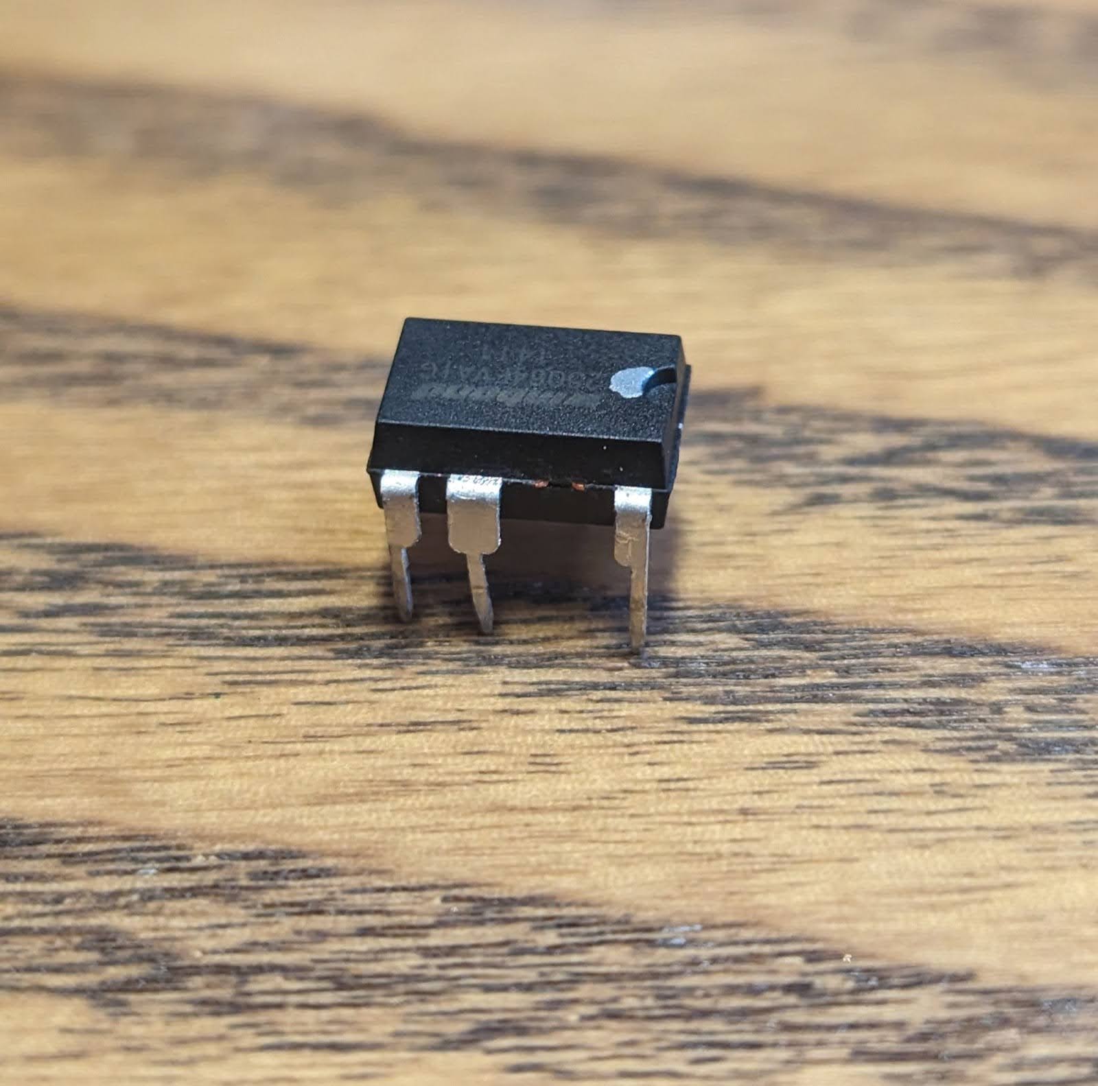
I had access to some older retired PCs that were using Winbond SPI flash chips, connected via DIP (Dual In-Line Package), making them easy to remove for testing. Using a SPI flash reader/writer designed for this task is the best option (e.g. such as this one from Dediprog, though it carries a much higher price tag). However, I wanted to test reading a SPI flash chip using the Bus Pirate, and my Bus Pirate SPI flash reading kit has not yet arrived, so I used a workaround:
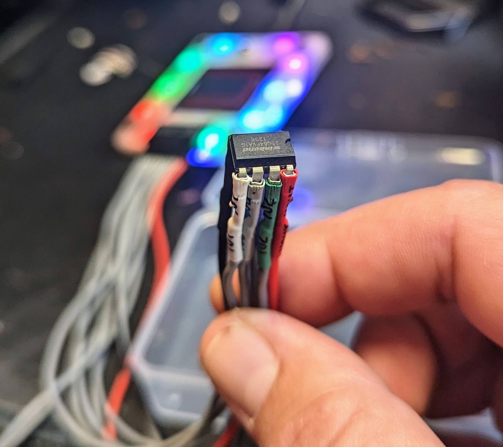
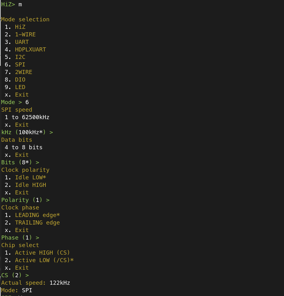
Again, this is not the recommended method, but I can attest that it does work (however, be gentle! See the disclosure section below). I had a few Winbond W25Q64 chips to read, which is a standard SPI flash chip and well-documented. I set the Bus Pirate to read this particular chip after carefully connecting the leads to the correct pins, being certain that only the pins that require voltage receive the correct voltage, otherwise you will end up making “magic smoke”:
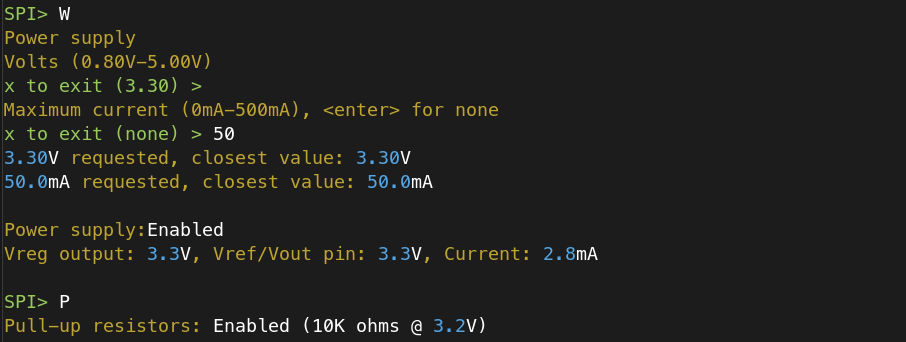
Next, I enabled voltage on the VCC connection and a pull-up resistor to send power to the correct places:
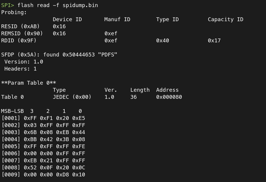
Next, I used the “flash” command to read the contents of the SPI flash chip:
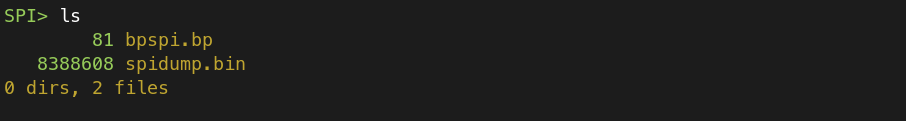
SPI> flash read -f spidump.bin
And successfully read the contents into the file specified above:
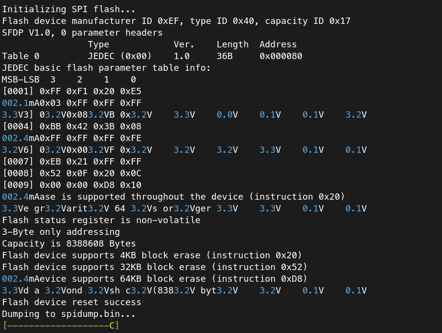
The file is then stored on the internal flash:
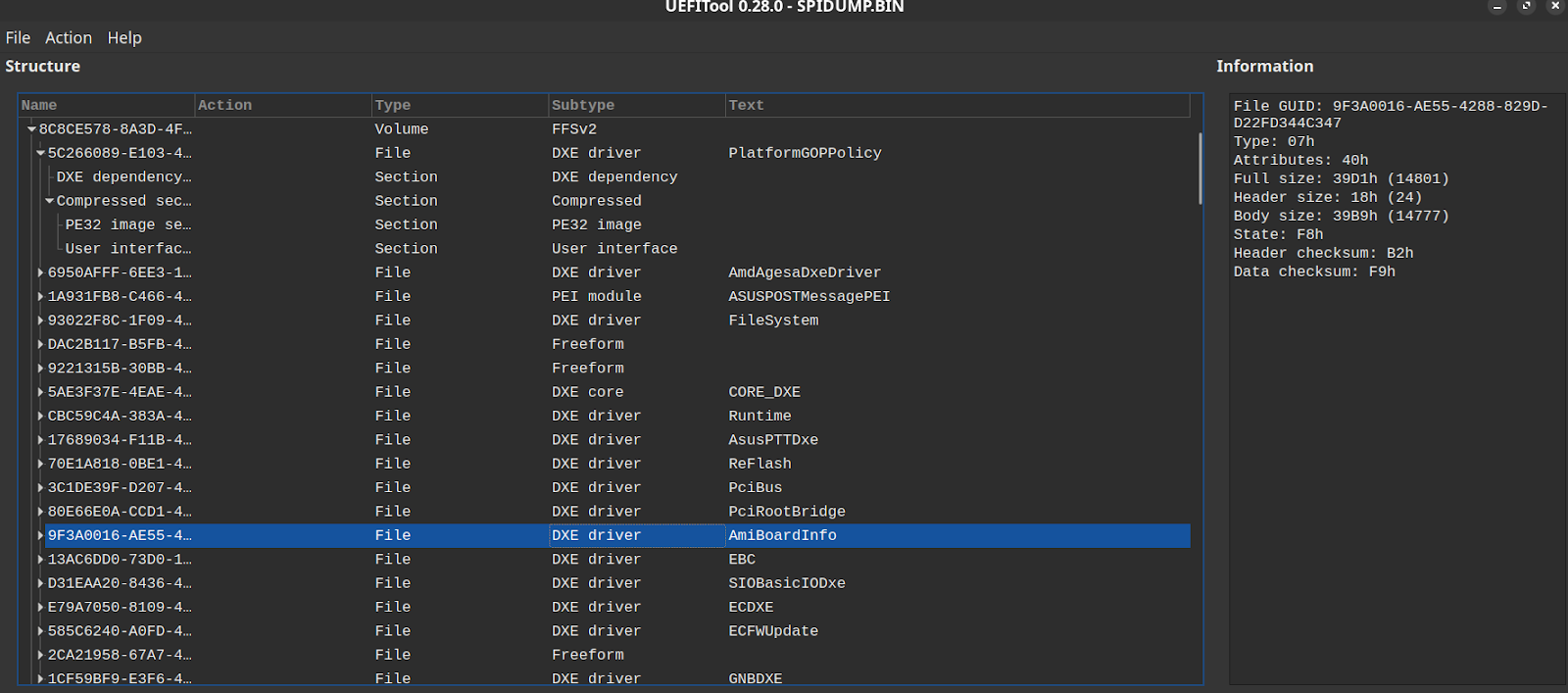
Disconnecting from the Bus Pirate serial console should allow your operating system to read the internal storage on the Bus Pirate to transfer the file (Though there are some known bugs with this feature). I then verified that I got a UEFI dump using UEFITool:
Bus Pirate Tips
- File system access can be a little “weird”. The internal storage is accessible via the terminal interface when you are connected to the USB UART. If you disconnect, the internal storage should show up as a drive mounted to your computer. I had to disconnect the Bus Pirate from USB and then re-connect it to the computer in order to copy over the SPI flash dump.
- There was one instance where it was not able to read the internal storage at all, either via the USB UART or my computer. I had to reset the device and re-flash the firmware.
- If you hold down the button in the back and then plug it in via USB it will come up in bootloader mode and allow you to re-flash the firmware (I had to do this once).
- Be certain to review the documentation to ensure the correct connections and proper voltage, for a SPI flash check out SPI Protocol Commands and the demo W25Q64 SPI flash board.
Conclusion
The Bus Pirate 5 is a handy device to carry with you (and all the various cables and connectors) for interfacing with a variety of platforms and connectors. Users should be diligent about checking for the latest firmware updates as development is very active, typically releasing new firmware every week. Despite some hiccups, the Bus Pirate 5 is useful for many different hardware hacking projects and debugging firmware/hardware issues.
Disclosure
Unfortunately, chips were harmed in the making of this blog post. The pins on the SPI flash chips I was working on are very delicate. Again, my recommendation is to use the hardware kits referenced above rather than connecting the barrel connectors directly to the SPI flash chip!
Resources
- Bus Pirate firmware updates
- Attaching to a Raspberry Pi’s Serial Console (UART) for debugging
- Bus Pirate 5 Tutorial – Basics
- Order The Bus Pirate 5 (and all accessories)
- Flashing a BIOS chip with Bus Pirate (Older Hardware)
- Projects Featuring The Bus Pirate (Mostly the older version):
- Getting the router shell using UART interface and bus pirate
- Hardware hacking tutorial: Dumping and reversing firmware
- 5-Min Tutorial: Lifting Firmware With The Bus Pirate
- BasicFUN Series Part 1: Hardware Analysis / SPI Flash Extraction
- Firmware extraction from SPI flash
- Dumping flash from a WAG45G
- Repairing a bricked EdgeRouter